Commercial
![]()
![]()
Domestic
![]()
![]()
About
![]()
![]()
Support
![]()
![]()
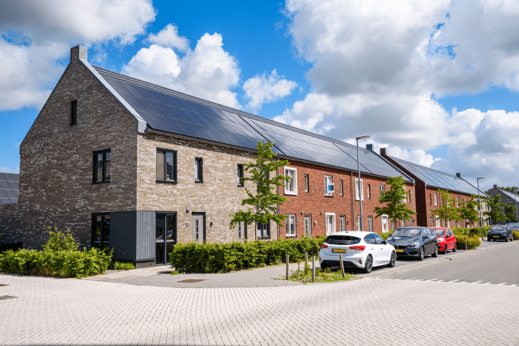
Take control of ever-rising energy costs and become more self-sufficient by harnessing the power of solar and renewable technologies for your home.
We provide industry-leading solar and energy solutions with a focus on quality, efficiency, and long-term savings. Here’s why customers trust us:
With years of experience in solar PV, battery storage, and renewable energy, our team delivers reliable and high-quality installations.
Every project is tailored to suit your energy requirements, ensuring the best return on investment for homes and businesses.
We use only high-performance, durable solar panels, batteries, and EV chargers from trusted manufacturers, offering the best warranties available.
From consultation and design to installation and aftercare, we handle everything, ensuring a seamless experience.
Our energy solutions reduce electricity costs while offering ongoing support and maintenance for peace of mind.
We’re committed to helping you reduce your carbon footprint and transition towards a cleaner, greener future.
Solar panels harness the power of the sun to generate electricity for your home. Solar panels, typically installed on your roof, capture direct current (DC) electricity from the sun. This is then converted by a solar inverter into alternating current (AC) — the type of electricity used to power your appliances. Any surplus electricity can then be exported back to the national grid which can earn you export payments through Solar Savings. You can also harness and store any surplus in a battery for later use or can divert the power to heat your hot water or charge your car. Additionally, surplus power can be exported to the grid, which can earn you export payments.
Investing in solar has a multitude of benefits, both for you and the planet:
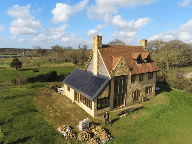
No matter what space you have to fill there is a solution for everyone
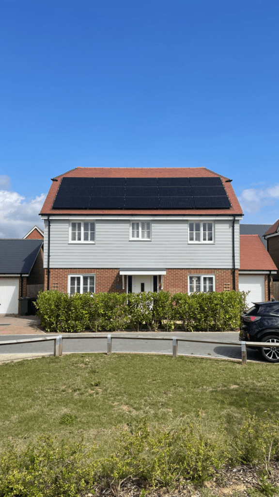
A cost-effective and efficient way to generate renewable power by installing solar panels directly onto your existing roof structure.
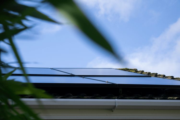
Designed to sit flush with your roof, in-roof solar provides a modern, aesthetically pleasing solution while delivering clean, renewable energy.

Ideal for businesses and properties with available land, ground-mounted solar systems offer maximum efficiency and scalability for renewable energy generation
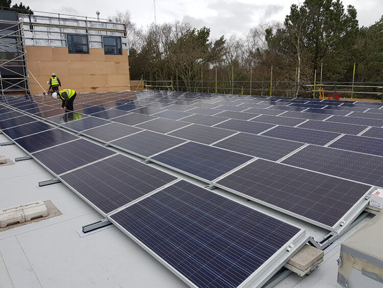
Designed for commercial and residential flat roofs, this adaptable solar solution maximizes energy generation without compromising roof integrity
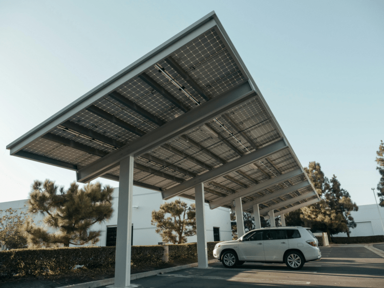
Generate renewable energy while providing covered parking, combining sustainability with practicality for businesses. Combining EV charging for staff and fleet vehicles
Every home is different, but whether you have a small roof or a sprawling one, there are solar solutions that can be tailored to your needs. Our expert team can guide you through the process — from assessing your property’s solar potential to explaining battery storage, EV chargers, and other smart energy solutions.

Harness and store your power for night time usage and cloudy days

Experience energy independence with the Tesla Powerwall 3—a high-capacity, intelligent battery designed to store your solar energy, reduce reliance on the grid, and provide simultaneous charging of multiple appliances. The Tesla Powerwall 3 is the smartest of batteries, offering whole-home backup power when you need it most.

Maximise your solar energy, reduce reliance on the grid, and stay powered during outages with SolarEdge’s smart battery solutions. Designed for seamless integration and efficiency, these batteries give you complete control over your energy.
Charge your Tesla or any compatible EV faster, smarter, and more efficiently with the Tesla Wall Connector. Designed for speed, convenience, and seamless integration with solar and Powerwall, it’s the ultimate home charging solution.

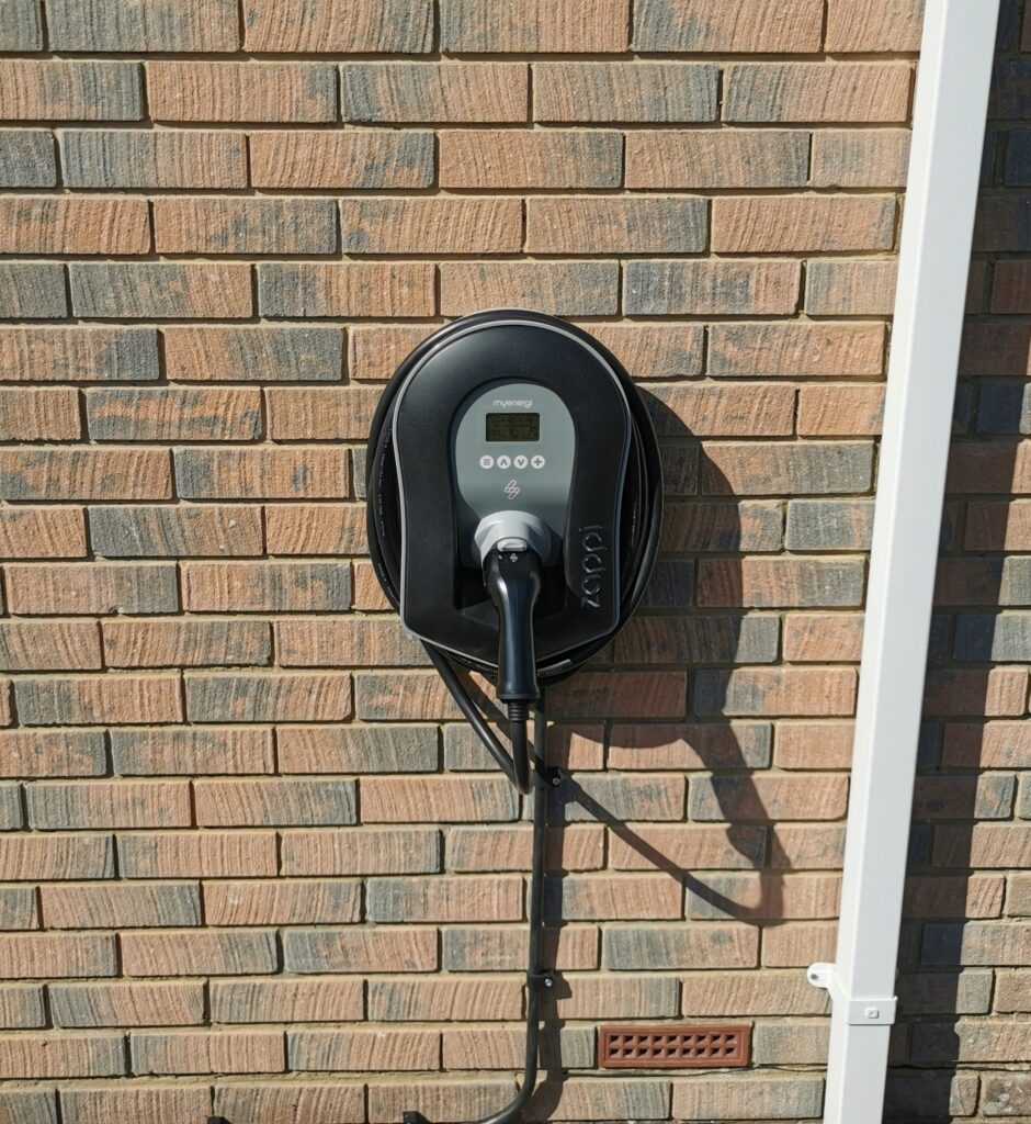
Charge your EV the smarter way with myenergi’s zappi, the home charger that charges on surplus power from the sun.
Take full control of your solar by redirecting surplus solar power to heat your water tank. The myenergi eddi helps you use, store, or sell your energy efficiently—cutting costs and increasing savings.

Our friendly team are here to help and advise on what the the best solution is for you

Specialists in innovative design and seamless installations since 2010

© 2025 Empower Energy Ltd


